


Mfr Part # 6100
SPARKLE MOTION PCB ANTENNA
Adafruit Industries LLC
License: See Original Project Addressable LEDs LEDs / Discrete / Modules Microcontrollers Wifi Wireless WS2812/SK6812 (NeoPixel) Arduino
Guide by Erin St Blaine
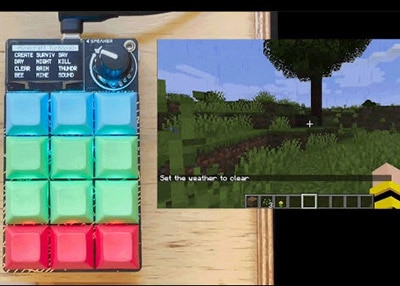
WLED and the line of Adafruit Sparkle Motion boards make it easy to control NeoPixels LED lights and build any project you want. The software is free, easy to use, and gives you a lot of options for light palettes, colors and effects.
If you're like me, you don't stop building after just one project. My living room has between five and ten WLED instances running at any given time, and I have several more that I bring to festivals, fairs or galleries to share with the public.
These different light projects and art pieces are easy to sync together with WLED's built-in sync features, and control from any smart phone or web browser. But this requires that I know where my phone is, and also that I know how to log in and use the software.
With this project I have been able to give control to anyone who comes in contact with my art, including kids that don't have a smart phone yet.
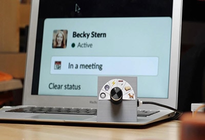
This wireless control button makes my art installations interactive over WiFi -- any audience member can now change animations and interact with the art in a fun, accessible way.
1 x USB C Cable
3 x Hook up Wire
Get wire in 3 different colors, to make your life easy.
This button can be powered by a USB-C battery or by plugging it into a USB wall charger. Using a battery makes it perfectly mobile, but WLED is a power-hungry program so don't expect it to last for days on a single charge.
An enclosure to house the button, Sparkle Motion and battery - I used a carved wooden vase, but you could also use a Tupperware bin, a jar, or make yourself a fancy 3D printed enclosure
Hot glue & black tape
A soldering iron + accessories
For testing: alligator clips & a coin cell battery
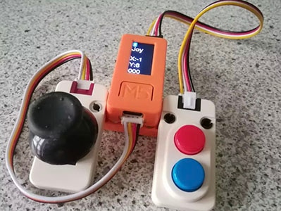
I also made a smaller version using a tiny QT Py ESP32 Pico board and a tactile momentary switch button. This version is easy to hide in your pocket so you can change effects or control the lighting with the stealth and cunning of a magician.
1 x Battery
1 x Battery Charger
A zip tie or two
Soldering iron & accessories
WLED works over WiFi, so these buttons will work perfectly in your home or within a known WiFi network. To take it out to a festival or event, you'll want to bring a WiFi router to facilitate communication between your devices. You don't need it to connect to the internet -- just to talk to all your different microcontrollers and keep them in sync.
This router from TP-Link is affordable and does the job. Look for a higher-powered router if you need to communicate over a long distance.
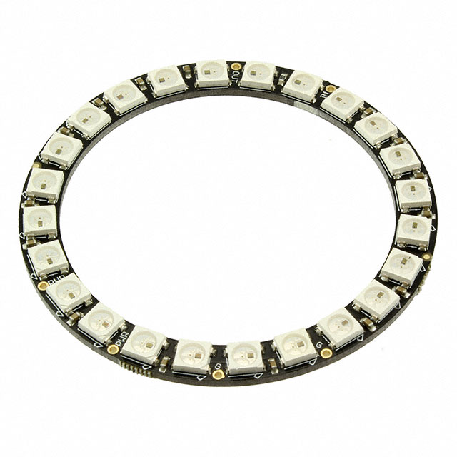
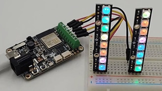
Connect your NeoPixel ring as shown: Pwr to +, Gnd to -, and DIN to GPIO 19.
The large arcade button has four connection pads: two for the internal LED and two for the switch. Connect the cathode of the LED (the longer leg) to -, and the anode to one of the available + slots on the screw terminal.
The pins on the screw terminal are output only, so we need to use a different GPIO to read the button presses. GPIO 18 is perfect for this. Connect one side of the switch to 18, and the other to G (labeled as -) on the screw terminal.
Solder the male JST connector to the back of the board, matching the + and - pads and making sure they line up correctly with your red and black battery wires.
Solder the legs of the momentary switch directly into pins G and M0, to keep the project as compact as possible.
This page will guide you through how to install WLED on the Sparkle Motion and QT Py ESP32 Pico.
For WCH USB to Serial chips:
The Sparkle Motion and QT Py ESP32 Pico have a USB to serial chip which may need a driver installed before you can install WLED. Head over to the How to Install Drivers for WCH USB to Serial Chips tutorial and download and install the new driver.
These next steps require a Web Serial-compatible browser. As of this writing, that means Google Chrome, Microsoft Edge or Opera “desktop” browsers. Other browsers (Safari, Firefox, Explorer and anything mobile) won’t work.
Visit https://install.wled.me/
Plug your microcontroller into your computer with a known good USB cable. Click "Install" and select the port for your board.
Depending on the USB-to-serial bridge chip on the board, you might see one or two serial ports. On Mac, for instance, there might be both “/dev/cu.usbmodem[number]” and “/dev/cu.wchusbserial[number]”. Use the “wchusbserial” one.
After successful installation, enter your WiFi network name and password when prompted. This must be a 2.4 GHz WiFi network; ESP32 does not support 5 GHz networks. If it can’t connect, then as a fallback WLED will create its own 2.4 GHz WiFi access point.
If you don't see the "Connect to Wi-Fi" prompt, you'll need to set up your WiFi network using AP (access point) mode. Open up your WiFi settings and look for a WiFi network called WLED-AP. Connect to this network using the default password wled1234. The WLED interface will pop up in its own browser.
From here, go into Config/Wifi Settings and enter your WiFi credentials near the top. Give your project a name in the mDNS field a little further down the page. Now you can type in "projectname.local" (where "projectname" is your mDNS name) into any web browser on the same wifi network to access your microcontroller.
You can also scan the QR code below to open access point mode.
For more help and troubleshooting tips visit the Getting Started page on the WLED knowledge base.
Head to the WiFi Setup screen under Config and create a good URL so you can control your project from any web-enabled device. Call it something you'll remember, that's easy to type into any web browser on your WiFi network in order to connect to your project.
In Safari or Chrome on your phone or computer, type in this web address to access the WLED interface: http://projectname.local (where "projectname" is whatever you put into this field).
Check out the Additional Settings page for more info on accessing your project. WLED has an "access point mode" that doesn't require a WiFi network for when you're out on the go. It's also helpful to download one of the WLED apps to help manage and organize your projects.
Next, head to the LED Preferences tab under the Config menu.
Scroll down to Hardware Setup. Put your total number of LEDs into the Length field (24, for the NeoPixel ring we're using) and change GPIO to the GPIO NUMBER associated with the LED data pin on your board. For the Sparkle Motion we used 19. Make sure to select the correct color order as well.
There are no lights connected to the QT Py so you can skip this step if you're making the mini version.
Now you can use any computer or handheld device to control your LEDs.
Make sure your device is on the same WiFi network as your board. Navigate to your custom URL (projectname.local/ ) in a web browser. You'll see a color picker above a whole bunch of color palette choices.
Choose a color, choose an effect, and watch your lights animate and glow!
Save your favorite combinations as presets, create playlists, control the speed and intensity of the animations, and lots more. This web app is incredibly intuitive and easy to use.
Head over to the WLED wiki at https://kno.wled.ge/ to delve into all the particulars.
If your lights didn't come on, here are a few things to try:
Head back to WLED and check your pinout configuration under LED Preferences. Be sure the pin number is the correct GPIO for the attachment point you used.
Check your wiring! Be sure you connected to the IN end of the LED strip. These strips can be inconsistent, so this is a pretty common problem. Use an alligator clip to try connecting the data wire on the other end (the power and ground wires should work from either end).
Try re-uploading the WLED software.
If the lights come on but you can't control them: i.e., you type in "projectname.local" into your browser and it won't connect, make sure you're on the correct WiFi network. If you're on a different network than the one you set up the software on, you won't see the WLED connection.
If your lights came on in blue or green instead of yellow, your color order is wrong. See below to fix.
If only half your lights came on, be sure you've got the correct number in the "length" field under LED preferences.
If your lights came on in a variety of weird colors and looking like a 1950s diner interior, you may have the wrong LED strip type selected. RGBW strips and RGB strips are not the same, so be sure you've got the correct strip type, or you'll get very odd behavior.
If your microcontroller hangs or keeps rebooting, or gets really hot, you may have the power and ground lines switched. Unplug right away and check: this is a fast way to brick your controller.
Wire up your NeoPixel ring as shown: a red wire to PWR, a black to GND, and a white wire to DI (data in).
The massive arcade button comes in two pieces: the large button enclosure and the switch assembly. Remove the assembly from the button (twist and pull) and take a look at it. There are four connection points available: two go to the onboard LED, and the other two go to the switch. The points aren't well marked so I used some alligator clips and a coin cell battery to figure out which were connected to the LED's anode and cathode side.
Solder a red wire to the anode and a black wire to the cathode. There's already a resistor in there so we can power this LED from any of the power pins on the Sparkle Motion.
Here's a guide showing how these buttons work, if you need more help.
The remaining two pads go to the switch. Solder a green wire to one pad and a black wire to the other. These two are interchangeable (the switch simply connects them together when pressed) but the color coding will help you get everything connected to the Sparkle Motion correctly.
Connect the ring to the Sparkle Motion. Use the first three ports on the screw terminal to connect the LED ring: red to +, black to -, and white to GPIO 19.
Connect the LED wires on the switch to a free + and - terminal: red to + and black to -.
Connect the switch wires: black to the remaining - terminal, and green to pin 18, along the side of the screw terminal. We can't use the screw terminal data GPIO since the pins they are output-only.
Use hot glue to secure the ring to the underside of the arcade button. Attach the switch assembly to the button, wrap the wires around and use a zip tie to attach the Sparkle Motion board to the switch.
For my setup, I added a right-angle USB C connector, so the cord hangs down instead of sticking out to the side. Your setup will depend on your enclosure.
Finally, I added a layer of black gaffer's tape around the Sparkle Motion board and wires before hot gluing it into my vase enclosure. The vase has openings in the sides where the light ring's effects can be beautifully seen, but seeing the electronics inside spoils the effect a bit. The black tape makes it all look a little cleaner.
Solder the JST connector and switch directly to the pads on the QT Py ESP32 Pico. This makes for a very small form factor which is easy to hide in your hand or your pocket, with no distracting wires or lights to give you away.
Flip the QT Py over so you're looking at the back. Trim two of the legs off the momentary switch. Solder the remaining legs to pins G and M0 (aka 13) -- the legs should line up just right with the holes. Make sure the button is placed above the board and not sticking out on the side.
Find the tiny + and - pads on the back of the board behind the USB port. Solder your JST connector + and - pads or legs onto these pads. Be careful - you don't have a lot of room, and if you bridge the pads with solder you'll short out your project.
I found it helpful to momentarily plug the battery in to the JST port before soldering; to be sure I had everything the right way around. Don't solder + to - or you could fry your board.
Plug your battery into the JST port. I added a zip tie around the battery to keep the wires from pulling out. Test to be sure it's working, then secure the battery to the board with another zip tie, keeping the button accessible.
You could also add a tiny on/off switch, but I like to keep it small and simple -- simply unplug the battery to turn the device off. It will drain the battery the whole time it's plugged in, since it's constantly "listening" over WiFi. But it will last long enough that you can impress people with your "magical" control of your lights.
"Presets" refer to a particular combination of animation, color palette, and speed/intensity/brightness settings. Making presets is a lot of fun: you get to play around in WLED and find settings that suit your style.
"Playlists" are a scripted list of Presets that will play in a specific order (or shuffle) for a specified amount of time. WLED gives you a lot of control. You can also set your playlist as the default setting when WLED boots up, so you can just turn them on and go.
In order to change the lights on your network, you'll need to set up the presets on your button controller, and not just on the lights you're controlling. More detail about this later.
Play with the effects and colors until you have the lights in a mode you want to save. Click over to the "presets" tab and click "+ Preset". Give it a name and save it to your list.
Once you've saved a few presets, you can string them together into a playlist. The playlist options include the ability to set your duration (how long each preset plays) and the transition time.
Take note of the number assigned to your playlist. In the next step you'll set up WLED to default to this playlist on startup.
Head to Config --> LED Preferences and scroll down until you find the Defaults section. Here you have an option for "Apply preset 0 at boot". Enter the number of your playlist here and click "save". Now when you boot up WLED your playlist will load first automatically.
You can also control the default brightness here. If you're finding your battery life to be too short, turning the brightness down will help.
Create at least 3 presets and be sure they are saved to ID numbers 1-3. Our next step will be to set up the switch to toggle between these presets.
The WLED preset interface can also be used to send control commands to the LED strip. Once you've set up a button or switch, it can be used for a wide variety of control functions: change modes, change brightness, toggle the lights on and off, or a whole host of other features.
Each button function in WLED has 3 options: a short press, a long press, or a double press. I want my lights to cycle through presets with a short press, and to turn on or off with a long press. Here's how I set up a control preset for each of these features.
Click +Preset and then uncheck the "Use current state" checkbox. This will open up an API command window within the preset module.
Call the effect "Next_FX" and type {"ps":"1~3~"} into the API command box. This tells WLED to cycle through presets 1-3. If you'd like to cycle through more presets, change the 3 to the number of presets you have.
Be sure your preset IDs include all the numbers -- skipping a number will break this command.
Give the Next_FX preset an ID number that's above the range of your other preset numbers -- I called mine 9.
It's also possible to cycle between playlists. I made a playlist of sound reactive effects and a separate playlist of "standard" effects. I set up a preset that toggles between the two playlists -- effectively turning "sound reactive" mode on and off.
Create another preset and call it "Toggle". Uncheck the "use current state" checkbox and enter T=2 into the API command box. This will tell the LEDs to toggle between on and off.
Find out more about creating these control presets here:
https://kno.wled.ge/features/presets/
You can enter either JSON commands or HTTP commands into this command box, giving you a lot of control over your WLED project.
https://kno.wled.ge/interfaces/json-api/
You can use a button in WLED to control various settings.
Open up the LED settings screen in WLED under "Config". Scroll to the button setup section and set button 1 to use pin 18 (Sparkle Motion) or pin 13 for the QT Py Pico (also known as M0 -- find the number on the pinout diagram), with the type set as "Pushbutton".
Click Save. Try pressing your button and see if your effects change.
The default behavior for button 1 is to cycle through effects. However, you can change this and set up the button for any number of behaviors using the Button Actions.
Next, head to the Time & Macros config screen. Scroll down to the Button actions area.
For your button, enter the number assigned to your control presets.
For example, here an "advance effect" preset is number 22, so 22 is setup under "short press". Then, a "toggle" preset is number 21, so 21 is setup as a "long press". A "playlist toggle" to preset 20, so a double-click of the button will turn sound reactive mode on or off.
If your button isn't working, here are some things to try:
Double check both the LED preferences page and the Time & Macros page to be sure your settings are correct and have saved.
Be sure your presets are correctly numbered. WLED gets confused if the presets have non-sequential IDs (so make sure they're numbered 1, 2, 3 rather than 2, 5, 7).
Head to Config / Sync Settings. Here you will set up the button so that it controls other instances of WLED that are on the same WiFi network.
There are 8 different sync groups available. For now, use group 1.
In the next section, you have the option to sync only the colors or the palettes and not the effects -- some effects look too busy on one project but just right on another, so this can be useful when creating a "scene" with multiple light projects.
Click "Enable sync on start" and "Send notifications on button press or IR" so the other instances change when you press your button.
Head back to the main control screen and click the Sync button at the top. Now any animations or presets running on your button controller will be pushed out to other instances in Sync group 1 on the same WiFi network.
Check to be sure the lights you want to control also have the "receive" box on Sync group 1 enabled. Also make sure none of your other projects have this Sync box checked -- WLED can get confused if two projects are trying to be the Sync controller at once.
I'm controlling a few different art pieces in my living room that each have their own presets and modes already set up. I was hoping I could send a command with the button that simply calls the next preset on the receivers, but that's not the way WLED works. If you want to control your projects with this button, the presets need to live on the button's controller - it can't send commands to use local presets on other controllers.
Instead, I needed to copy the presets over to my button's controller. I did this efficiently by running this process in reverse: I turned on the Sync "send" command on the existing art and then the "receive" command on my button. As I selected each preset, WLED would receive it on the button controller, and I could save it as a preset on that controller.
This was a fast way to re-create all the presets I wanted to collect from my other projects and store them on the button controller. Once all the presets were saved, I turned off sync on the existing pieces and turned it back on on the button controller, and I was in business.
This button makes your art pieces interactive, as long as you're on your home WiFi network. If you want to take it out and show it off to the world, the easiest way to stay connected is to use a proprietary WiFi router. This will allow you to set up your own local WiFi network. It doesn't need internet connectivity, so you don't need to hook it up to an internet account or Ethernet cable -- just power the router up and you'll get a LAN (local network) which all your WLED instances can use to communicate with each other.
Each WLED instance has WiFi credentials set up in the WiFi Setup screen. To make my life easy, I gave my portable router the same WiFi name and password as my home network. This way I don't need to change WiFi credentials when I'm away from home -- my projects will simply work whether I'm home or away. It does make it difficult to test the router setup from my house -- having two of the same network names creates a conflict -- but in the long run I'm glad I did it this way.
Each company has a different WiFi setup software package, so read the directions that come with your router. All you need to do is set up the network name and password and then make the WiFi settings on your WLED instances match.
Now you can take your projects anywhere and sync them together or control them from your phone without needing to be within internet range.